Resonant Energy’s “Solar Ready” Definition for New Construction
By Katherine Wagner
Resonant’s recent work with a number of affordable housing developers has made one fact increasingly apparent: early coordination is key for the successful implementation of solar energy in new construction. The term “Solar Ready” has been used in the past to communicate to builders and developers that solar design has been factored into building plans; however, the definition of the term can vary widely. In this blog post, we will dive into what solar ready really means, when to start planning for solar, and who needs to be involved as we continue our work to provide solar access and energy savings to our community.
KEY PLAYERS
At the start of a new construction project, there are many individual contributors to the final design. From the very beginning of a solar project, developers, general contractors, architects, engineers, electricians, plumbers, HVAC, and roofers are all involved in decisions made to make a project “solar ready.”
To help ensure that the building effectively includes solar design parameters, we suggest property developers consult Resonant once construction drawings are 50% complete. At this point in the process, we can address questions like, “What roof material is preferred,” “Where do I need to locate vents and HVAC to best reserve space for solar panels,” etc.

GETTING STARTED: DESIGN PHASES I & II
After a letter of intent has been signed and we receive 70%-100% complete construction drawings, Resonant will begin Design Phase I. Together we will review the construction drawings to identify the following items and recommend any necessary modifications to the construction drawing sets to incorporate solar design:
Structural:
Additional dead load bearing capacity of the roof in lbs/sqft (PSF). Note: for sloped roofs, we recommend min 5 PSF; for flat we recommend min 10 PSF
Electrical:
Behind the House Meter: The most common tie-in strategy for solar PV is to have a dedicated breaker (typically 150-200 amps for most multifamily projects) added to the house panel for us to back-feed. This is ideal based on the incentives in MA and also comes with the benefit of allowing us to complete our tie-in without shutting down power to the whole building for 8-12 hours.
Standalone Meter: it is possible to set up solar PV via a standalone meter and export the value of the electricity produced to other sites. This is much less common and requires robust advanced coordination to ensure the tie-in pathway is well planned for with the electrical engineer for the development.
Conduit:
Architects should include a 4” metal internal conduit from the roof to the electric room with as straight a shot as possible to be dedicated for solar PV as part of the GC scope.
Plumbing:
Vent Pipes - often can be moved. should be grouped in the middle of the flat roof or located as close as possible to the roof’s edge – or near other obstacles.
Roof Drains - generally can’t be relocated, but good to be mindful about placement to the extent possible as it will remove space where panels can be placed.
HVAC:
Equipment Placement: typically center spine of flat roofs and sited ground/attic for sloped roof sites. Most can’t be moved; however, choosing centralized VRF systems in lieu of single heat pumps for every unit can A) centralize load for solar to offset on the common meter and B) significantly reduce the amount of roof space needed for HVAC - leaving more space for solar.
Walkway Pads - typically can’t be moved, but are an obstacle for solar PV. Often not included in building drawings, so helpful to include if possible.
Gas Lines - can significantly disrupt solar and sometimes are not placed carefully. Be sure to highlight for the GC and subs to ensure no issues arise.
All other obstructions that would affect solar equipment placement
Roof Information:
Flat Roof Material Type: EPDM is the easiest to install solar on (can be procured in white if needed, though is most commonly black). White TPO is the most common material we’re seeing developers use due to its slightly lower cost, however, it can be challenging to install solar on this material due to the significant additional costs associated with waterproofing penetrations through the material compared to EPDM.
Sloped Roof Material Type: Asphalt is the most common material for sloped roofs.
Roof Material Manufacturer & Warranty: we need this information from the development team as soon as a vendor has been selected so we can proceed with the paperwork in advance of our installation to ensure that we preserve the roof warranty.
Additional Info: Roof slopes / tapered insulation depths are useful to know in determining the best racking type for the array. If not included in the designs, we will follow up. Greater slopes often mean that a fully ballasted racking design won’t work and we’ll have to have some penetrations.
Fall Protection:
Parapets & Rails: > 39” tall parapets and guardrails cover fall protection for ongoing solar maintenance needs; however, these are more expensive solutions and not frequently used, unless a parapet is required for other aspects of the building’s design.
Tiebacks: These are the most common type of fall protection used for solar and other fall protection needs due to their significantly lower cost. These should be placed either towards the center of the building or towards the outer edge (within 4’) to avoid impacting the space for solar PV. Note: you’ll always need one near the center of the roof where you enter so you can get to others on the roof safely.
Other:
Any other equipment that extends above the roof surface (e.g. antennas) or areas of the roof over which solar panels should not be installed (e.g. roof hatches) can pose a challenge as they are not always included in the full construction drawing set. In the past, we have seen this kind of equipment get installed without consulting solar and has resulted in losing modules.
Design Phase I
This first phase will yield a stamped preliminary electrical permit plan set which will allow us to apply for interconnection with the utility. After completing the Preliminary Solar Engineering Design, we will share the .dwg CAD files of the solar equipment placement. The solar equipment must be added to the architect’s building drawings so all parties are clear about where solar will be installed. Failure to capture all of these items in the initial design significantly increases the likelihood of future change orders and added costs.
Design Phase II
The second phase begins once the roof of the building has been completed and we can schedule a site visit with the solar installer. This site visit will identify what, if anything, has changed from our initial design plan to the as-built conditions and locations of roof obstructions. Based on past experience, changes from our preliminary plan set for interconnection and the final building design occur most commonly on flat roofs. New obstructions can often result in a solar design that is 5-10% smaller than earlier designs. Please see figure 1 for an example of changes made to a solar project due to new roof obstructions in the construction process. Reductions in system size beyond 5% will result in a change to the $/watt cost of the system (or, for systems financed through a no-cost Power Purchase Agreement (PPA), a change to the PPA year-one discount and/or PPA annual rate escalator).
With sloped roofs, final designs often closely match the preliminaries. To prevent reductions in array size, the Customer must hold their GCs accountable through planning and expectation setting to defend the roof space for solar and ensure the building is fully solar ready by the time we enter Design Phase II.
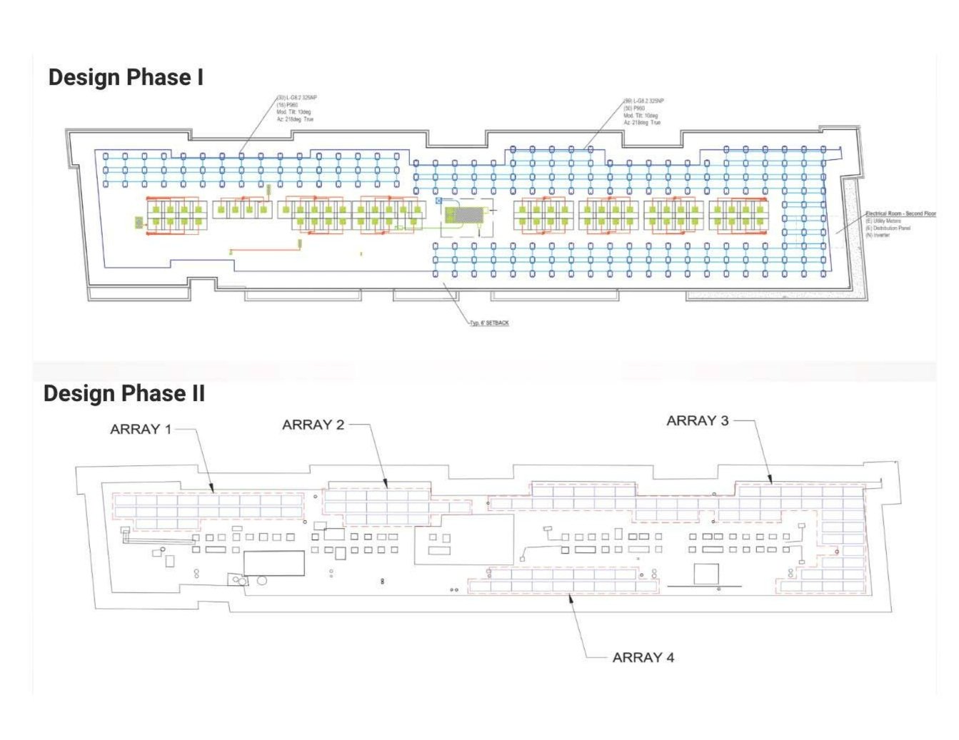
Figure 1. This is a photo of a new construction affordable housing solar project during Design Phase I and Design Phase II. As you can see, after the building was constructed and we performed a site visit, there were vent pipes placed in areas that conflicted with the solar array design from Design Phase I. This resulted in the loss of panels and a reduction in system size. Incorporating the solar design from Design Phase I into construction drawing sets is highly recommended to defend the roof space for solar and ensure all parties involved have the same design information.
SOLAR EQUIPMENT PLANNING/STAGING
While it is clear that building components and obstructions are an integral part of solar design planning, it is also important to plan accordingly for the solar equipment itself. Below is a list of equipment that will be added to the building as a result of installation:
Inverters: Can go on a roof penthouse (min 2.5’ off the ground), internally, or externally at ground level. Note: should be in a relatively shaded spot to avoid overheating and loss of productivity in the summer.
Conduit: If GC doesn’t have 4” metal conduit in their scope to get solar from the roof to the electric room, we will need to run an external conduit as part of our scope, which developers don’t typically like as much aesthetically. Note: if the electric room is not adjacent to the exterior of the building, the GC also needs to install 2x 2.5” metal conduits to allow us to get from the electric room to the exterior to locate a required disconnect switch for first responders.
SMART Meter and Disconnect Interior Placement: If the building has an underground service drop and the meter bank is interior, the utility will typically require “meter grouping” with the SMART meter inside and two disconnects (one outside and one inside)
SMART Meter and Disconnect Exterior Placement: If the building has an overhead drop and external meters, then the disconnect and SMART meter must be outside, near the meter bank (typically outside the electric room)
ROOF READINESS: STRUCTURAL PLANNING AND RACKING SOLUTIONS
Structural planning happens very early in the building process. Across all flat roof projects, an additional 10lbs/sf of dead load capacity should be added to the structural load for solar equipment. For sloped roofs, we recommend at least 5lbs/sf of dead load capacity. When included in the early phases of design, adding dead load capacity for solar will allocate the correct structural preparedness and will save both time and resources needed to reinforce the structural capacity of a roof later in the construction process.

Figure 2. Racking types and structural lbs/sf recommendations
Racking determines how many modules we will be able to fit on a given roof. Depending on the needs of the project, we will recommend different racking types. For flat roofs, we prefer fully ballasted racking. We have seen white TPO become a standard roofing material for new construction buildings and while TPO may check boxes for certain insulation and building standards, it can pose a challenge for solar installations. The most important component of installing solar on a flat TPO roof is to avoid the need for mechanical attachments to prevent drilling into the insulation and maintaining the integrity of the material.
For projects that require high energy density – for example, City of Boston E+ developments – wavelet racking is a premium option that allows more modules to be installed on the roof. This is the heaviest method for racking due to the concentration of modules and the ballast blocks included in the design. It is recommended to add 15lbs/sf of dead load capacity to the structural calculations.
We are excited and encouraged by the engagement to better define what it means for a new construction affordable housing project to be “solar ready.” Sharing our learnings and recommendations can only lead to better, more optimal solar installations in the future.